In the last post, I connected a CPU to a UART to print "Hello, world over this serial link. Even if the endeavor is quite fun, it's not as impressive as writing it on a screen. To do so, we would need some sort of GPU.
One of the easiest ways to send video to a somewhat modern screen as a VGA signal. It is quite simple to send a VGA signal, the pixels are sent to the screen one after the other, from left to right and from top to bottom.
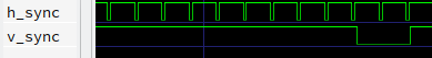
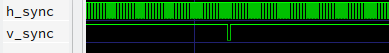
To tell the monitor which position on the screen we are trying to draw, two sync signal are used. On the h_sync line, a small pulse is sent after a full line has been drawn. On the v_sync line, a pulse is sent after the whole screen has been sent. The shape and the frequency of those signals are what define the refresh rate and the resolution.
Here are those signals from a simulation:
For each of the red, green, and blue parts of a color, there is an analog signal sent through a wire. On that signal, a voltage of 0 V means that there not of such colors and a voltage of 0.7 V means that this color should be fully turned on. For example, when writing a pixel with 0.1 V on the red wire, 0.7 V on the green wire, and 0.4 V on the blue wire, the pixel will be colored in a pastel-green color.
During a small time window around the sync signals, the voltage on the color signals should be kept to 0 V.
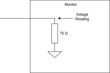
As the FPGA only has digital outputs, generating the analog color signals is not trivial. Fortunately, the input impedance of each color line is defined as 75 Ω in the VGA standard. This means that the input of each color can be represented as followed:
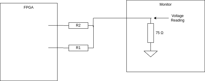
Thanks to that, I can put a resistor on the digital outputs of my FPGA to make a voltage divider that generates the desired voltages. I chose to have two digital outputs per color channel, resulting in 6-bit color. To do so each channel has this configuration of resistors:
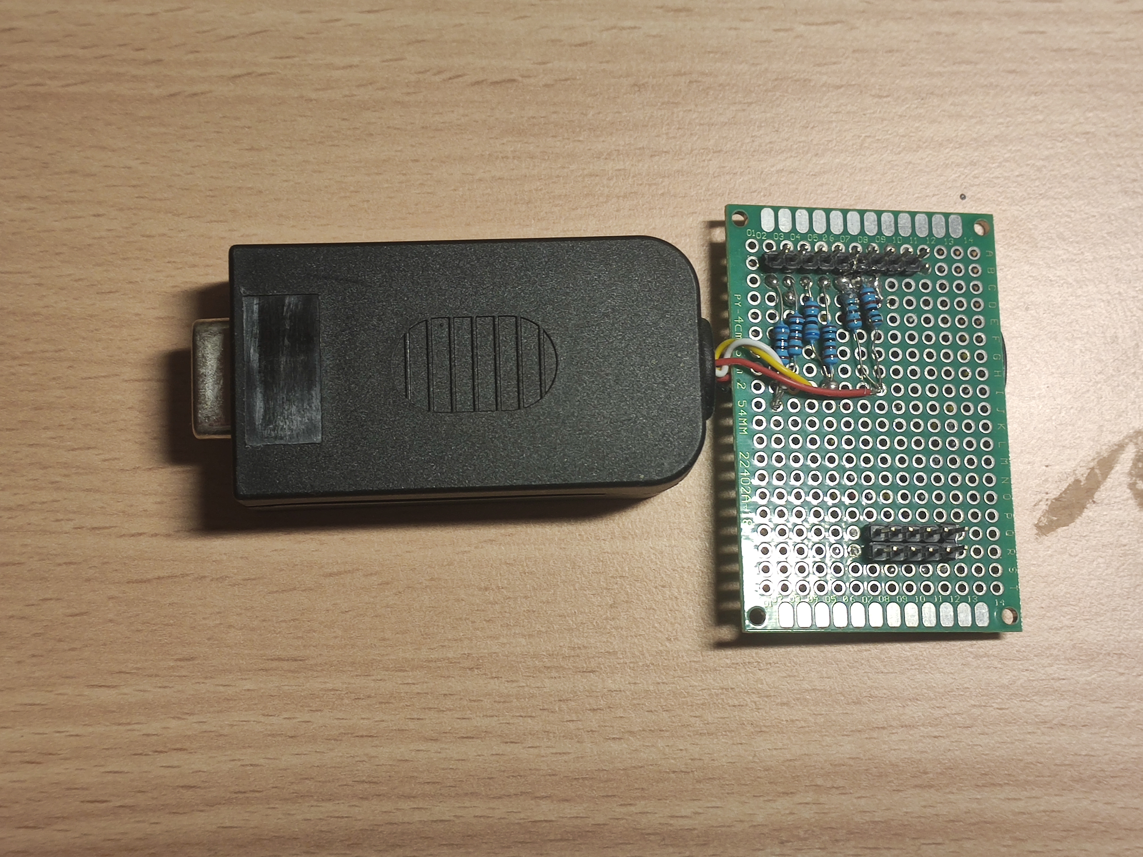
The resulting analog card looks like this:
Now that we understand how to send a VGA signal, we can make a GPU to control it.
The GPU got multiple modules. The most important one is the timing generator, which keeps track of which pixel is being drawn and sends the sync signals to the monitor. The information about which pixel is being drawn is then used to index various memories that store the colors to draw.
There are two layers in that GPU. Firstly, a bitmap layer. It simply stores a color for each pixel and outputs it when the timing generator gives that pixel.
Then, there is a text layer. That layer stores packs of background color, foreground color, and letter. When a pixel must be drawn, it first computes which letter it corresponds to, fetches it for memory, passes it through a character ROM to see if the pixel is in the foreground or the background of the letter, and then color it accordingly.
The combination between the two layers is made with α blending. The pixels on the bitmap layer as stored with RGBA components.
To update the content of the GPU's memory, two inputs taking X and Y coordinates are associated with inputs for color. Some registers are placed on the processor's memory bus to bridge between the CPU's output and the GPU's inputs.
Having two inputs for X and Y coordinates can seem like a bad idea, as a lot of memory accesses are needed to update each pixel. An alternative would be to present the GPU's memory on the CPU's memory map. This would require less memory access to update the pixels but it would take more space on the memory map and require multiplication to compute memory offsets. As the 16-bit processor I link to the GPU has limited memory space and doesn't have multiplication instructions, the solution I went with is better.
As the GPU takes input as X and Y coordinates and a color, controlling it is very natural and easy when doing pixel operation. Here is an example of code that draws a heart on the screen:
; Pairs of x-y coordinates used to draw a hearth. 1-indexed, 0-terminated
label hearth
@rawbytes         1 3 1 4     1 6 1 7
@rawbytes     2 2 2 3 2 4 2 5 2 6 2 7 2 8
@rawbytes 3 1 3 2 3 3 3 4 3 5 3 6 3 7 3 8 3 9
@rawbytes 4 1 4 2 4 3 4 4 4 5 4 6 4 7 4 8 4 9
@rawbytes 5 1 5 2 5 3 5 4 5 5 5 6 5 7 5 8 5 9
@rawbytes     6 2 6 3 6 4 6 5 6 6 6 7 6 8
@rawbytes         7 3 7 4 7 5 7 6 7 7
@rawbytes             8 4 8 5 8 6
@rawbytes                 9 5
@rawbytes 0 0

; Draw a hearth at coords 30 30
label draw_hearth
    ; Initialize useful constants such as pointer, color, and offset
    setlab hearth
    cpy R1
    setr R4 0x83
    setr R5 29
    setr R6 29
    ; Prepare the first pixel
    load8 R1
    cpy R3
    inc R1
    load8 R1
    cpy R2
    label hearth_loop
        ; Draw the current pixel
        read R5
        addup R2
        read R6
        addup R3
        callf gpu_draw_pixel
        ; Move pointer R1 and update target coords
        inc R1
        load8 R1
        cpy R3
        inc R1
        load8 R1
        cpy R2
        ; Check for null termination
        set 0
        eq R2
        cmpnot
        jifl hearth_loop
    ret
Here is the hearth on the bitmap layer along with a message on the text layer. Note the α blending between the hearth and the "L" of "Love".
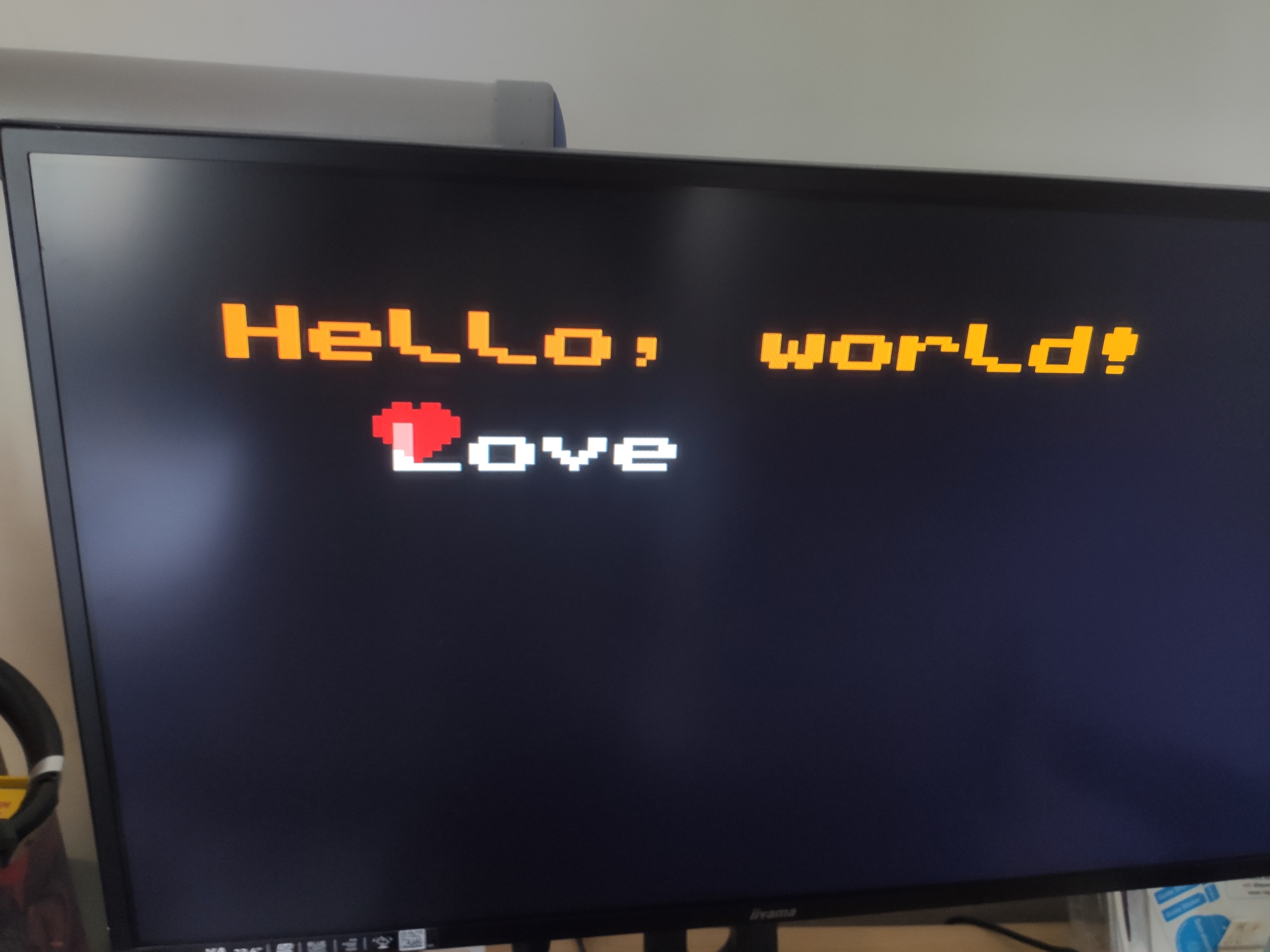
As those words appear on the screen, we can truly say we wrote "Hello, world!" from scratch.